3D Rotating Cube Project Files and Tutorial
***Please note that this tutorial is for the Windows OS only***
Download the 3D rotating cube project file by clicking here (download the most recent version). You’ll also need to download the free version of SketchUp (it’s called SketchUp Make and you’ll automatically get a 30 day free trial of the most recent Pro version).
The following tutorial will show you, step by step, how to customise the 3D cube so that you can personalise it for your website.
Step 1 – SketchUp Settings
Once you’ve downloaded the SketchUp project file, right click and select ‘open with SketchUp’. You’ll see the menu below:
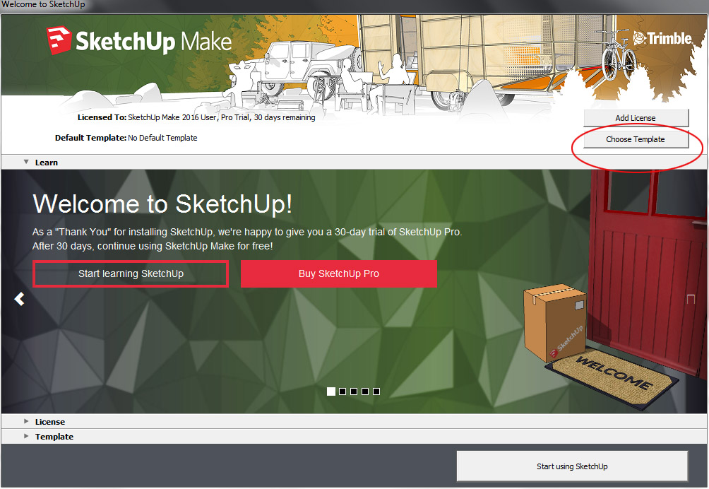
Click ‘choose template’, a dropdown list will appear, choose ‘Architectural Design – Millimetres’ and then click ‘Start using Sketchup’ (bottom right hand corner).
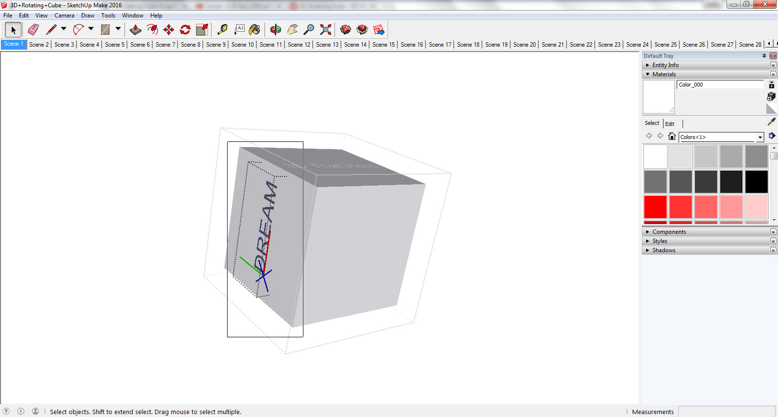
A ‘default tray’ will automatically appear on the right hand side of the screen, close it using the ‘x’ box.

Step 2 – A Quick Introduction to the SketchUp Interface
In order to customise the 3D cube for your own purposes, it’s important that you’re familiar with a few functions of the SketchUp interface. I will only be focusing on the functions that are applicable to this tutorial.
Scenes
Each Scene tab contains the individual frame for the rotating animation. If you click on the first few scenes, you will see the cube change position. For this animation, 47 scenes were required to facilitate the continuous rotation. You don’t need to worry about any of the other 46 scenes, only the first scene! Let’s keep things simple, eh? All of your customisation of the cube will be done using SCENE 1, all of the other scenes will be updated automatically to reflect all of the changes you’ve made in Scene 1.
If you select ‘view’, then ‘animation’ and then ‘play’, you can watch the animation within SketchUp. Click ‘stop’ on the pop-up menu to stop the animation.
If at any stage you need to go back to the original positioning of the cube, simply click on the tab entitled Scene 1, using the Selection tool (see below).

Selection Tool
You’re going to need this tool to make selections, either on the cube itself or to choose functions from the top menu.
Zoom
This allows you to zoom in and out of the current scene.
Orbit Tool
This will allow you to orbit around the cube to make edits.
Move Tool
Move or rotate a 3D component.
Paint Bucket Tool
This will allow you to change the colour of the cube, add your logo and select the colour of your 3D text.

Scale
Use this tool to scale or stretch a selected entity.
Undo
Go to ‘Edit’ and select ‘undo’.
Delete
To delete something on the cube, click on the Selection tool and then select the 3D component you’d like to delete, then press ‘delete’ on your keyboard.
Step 3 – Editing The Cube
This cube has been made into a ‘Group’, if you click on it using the Selection Tool, you’ll see that it will become highlighted in blue. You need to double-click the cube once you’ve selected it, to edit it (this is important when inserting the logo image and editing the 3D text).
Step 4 – Changing the Colour of the Cube
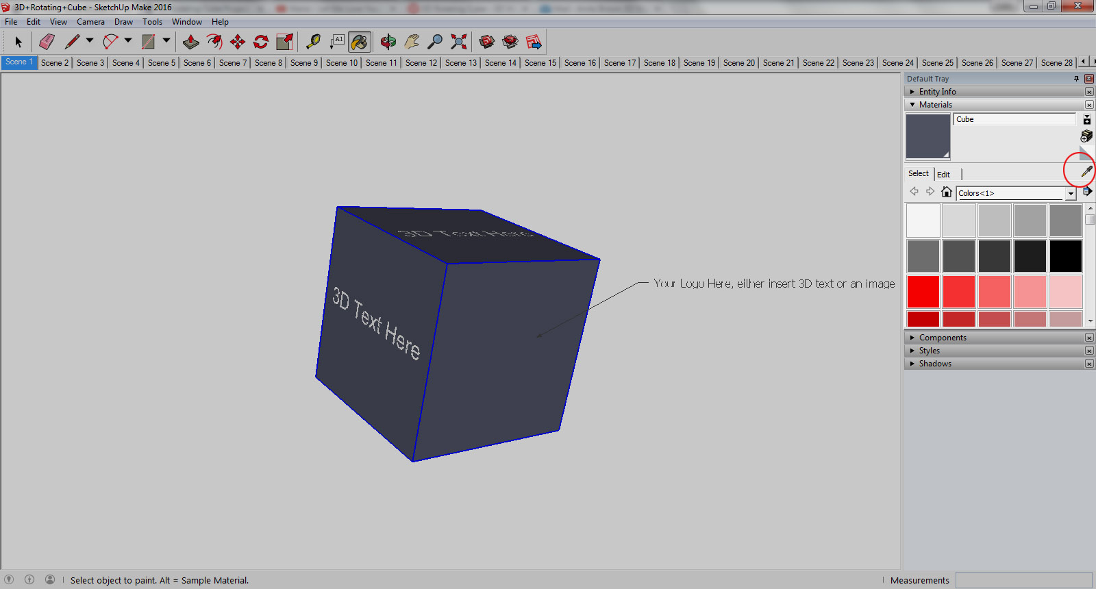
You don’t need to double click the cube to change the colour, Simply click the Paint Bucket Tool (the Default Tray will appear, close the Instructor subsection because it’s distracting) and then select the sample paint tool (circled in the image below). Click on the surface of the cube that’s blue JUST ABOVE ‘3D TEXT HERE’ and then select the tab entitled ‘Edit’, here you will see a drop-drown arrow, select it and choose how you’d like to select your preferred colour, by using RGB values or the colour wheel. As soon as you start editing these values, the colour of the cube will change accordingly.
Step 5 – Adding Your Logo/Image
With the ‘Materials’ tray still open, click on the tab ‘Select’ and then using the sample paint tool, select the face of the cube that has been designated for the logo. Then click the ‘Edit’ tab. Assuming that your image has already been saved to your computer, go to the section entitled ‘Texture’ and directly underneath, click the box beside ‘Use Texture Image’.
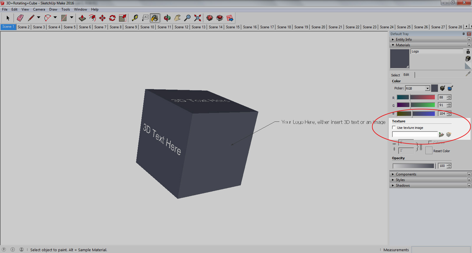
You will immediately be prompted to choose an image from your computer. Select the image. Depending on the size of your image, it will most likely need to be scaled and re-positioned to fit the face of this cube.
Double click the cube and select the face where the logo has been inserted. Right click and select ‘texture’ and then ‘position’.
Your scene should look something like this.
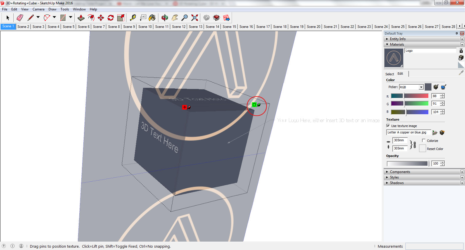
Hover over the green pin until the Selection Tool changes to a pointing hand, click and drag this pin until you have scaled the logo to your liking. To position the logo, click on the face and drag the Selection Tool. When you’re happy with the positioning, right click and select ‘done’.
The logo should now be central to the face of the cube, like this.
![]()
To view the logo/image at a better angle, click the Orbit Tool and rotate this face towards you, to make sure the logo is central. Repeat the above steps if the positioning of the logo still requires adjustment. Once completed, click the tab entitled ‘Scene 1’ so that you are viewing the cube in its original state. Using the Selection Tool, click on the text ‘Your logo here…’ and press delete on your keyboard.
If you’ve managed to successfully change the colour of the cube and have inserted your own logo/image, congrats! You’re halfway there!
Step 6 – Adding 3D Text
You’re probably wondering why the text insertions on the cube have been referred to as ‘3D’ when in actual fact they are 2D! It’s possible to extrude 2D text in SketchUp – the tool to place 2D or 3D text onto an object in SketchUp is referred to as 3D Text. Glad we cleared that up!
You’ll notice that I have annotated faces on the cube with ‘3D Text Here’ – these insertions cannot be edited, you’ll need to delete these and then insert your own text. Double click the cube, select ‘3D Text Here’ (it will be highlighted in blue) and then press delete.
Go to ‘Tools’ in the toolbar and then select ‘3D Text’. A new menu will appear. Make sure that ‘extruded’ is unchecked (unless of course you’d like the text to be 3D), ensure that ‘filled’ IS checked and enter 70mm for the height dimensions. Choose your preferred font from the drop-down list and then write the text in space provided.
Once you’ve entered your text and clicked ‘place’ the sub-menu will close and you’ll be prompted to place the 3D text onto the cube. You should have noticed that the Selection Tool will have changed to a cross shape, consisting of 4 arrows (Move Tool). Hover over the face and once you see the tag ‘on face’, click that area. The 3D text has now been attached to that face.

Double click the blue bounding box of the text (it may be difficult to see the text once placed because all edges have been turned off for the purposes of this particular 3D model), once you have double clicked, you should be able to see the text very clearly. Take the Selection Tool and drag a box around ALL of the letters to select them (the box you created with the Selection Tool is temporary and will disappear). All of the letters should have little blue dots on them which confirms that they’ve been selected.
Select the Paint Bucket Tool and choose the colour already selected (white) and then ‘paint’ the selected 3D text. You can then edit this colour using the ‘edit’ tab.
Once finished, click the Selection Tool and click anywhere on the white background behind the cube (click only ONCE); the 3D text should no longer be selected for editing but the cube component should still have editing capabilities.
For the purposes of this tutorial, it’s easier to have all 3D Text the same colour, if you’d like me to explain how to choose varying colours for different insertions of 3D Text, drop me a comment in this blog post.
Rotating the 3D Text
With the Selection Tool, click the 3D Text so that a blue bounding box appears, then click the Move Tool. Hover over the bounding box until 2 red crosses appear. Place the cursor over one of the red crosses, you’ll notice that the cursor changes to two curved arrows. Rotate the 3D Text 90 degrees clockwise – check the measurements box in the bottom right hand corner to make sure you have rotated exactly 90 degrees.

With the 3D Text still highlighted by the blue bounding box, scale if necessary using the Scale Tool to increase its size, using the corner grip. Repeat all of the above steps for the insertion of 3D Text for the remaining faces.
Once you’ve completed all of these actions, you’re DONE!
Step 7 – Exporting the Cube to make a Gif
All of the individual 47 Scenes need to be exported into either Adobe Image Ready or GIMP to create a Gif. I’m going to focus on Adobe Image Ready for this tutorial.
Create a folder on your computer so that all of the individual images exported from SketchUp can be saved into a dedicated folder.
In SketchUp, Go to ‘File’, ‘Export’, ‘Animation’ and then click on ‘Image Set’. You will be prompted to name the sequence of images and choose a folder. Then click ‘Export’.
Open Adobe Image Ready and go to ‘File’, ‘Import’ and then select ‘Folder as frames’. You’ll be prompted to select a folder. Select the folder containing all of the exported frames from SketchUp.
Change the frame delay time for ALL imported images to 0.07 seconds and crop the image so that there’s reduced white space. To save, select ‘File’ and ‘Save Optimised As’.
You’re now the proud owner of a rotating 3D Cube!


1 Comment
[…] experiencing any challenges when customising the 3D cube, drop a comment below or on the tutorial post and I’ll be sure to help you […]
LikeLike